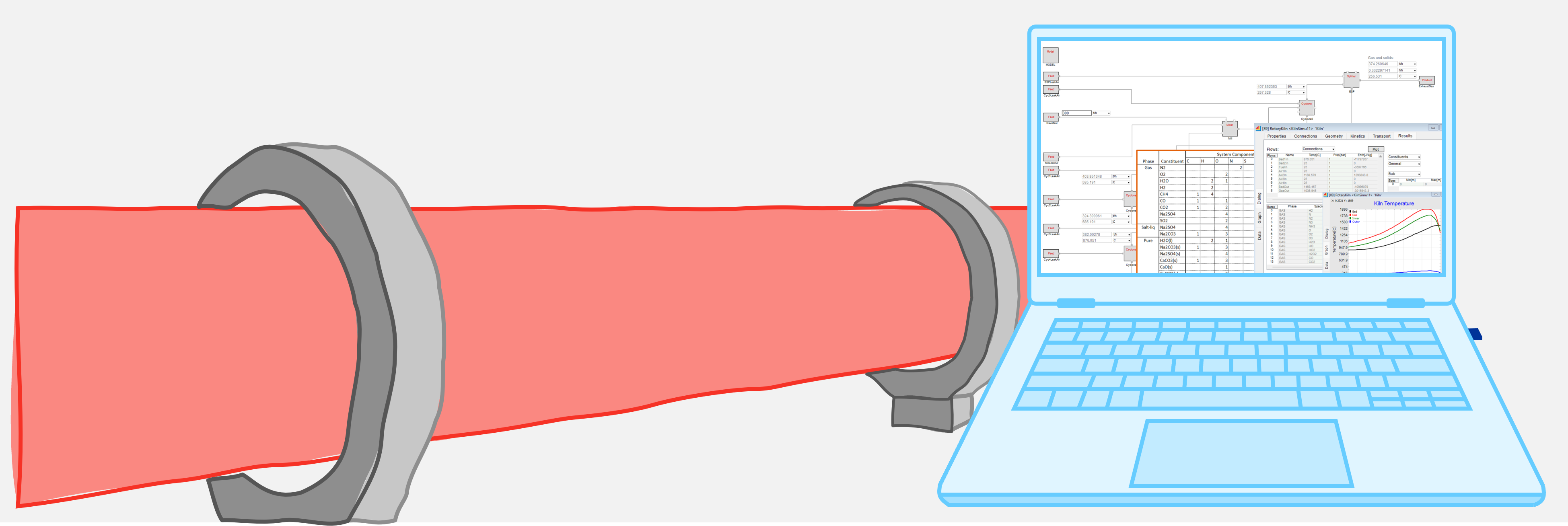
KilnSimu workflow: A step-by-step cement kiln simulation as a practical example.
In this section, we demonstrate the capabilities of KilnSimu through a detailed example of a cement kiln application. Step by step, the workflow is illustrated with comprehensive screenshots. Each block and tab within the software provides essential tools for optimizing kiln performance, from selecting the right fuels to fine-tuning process components. By exploring these sections, you’ll gain a comprehensive understanding of how KilnSimu enables detailed simulations to optimize energy efficiency, product quality, and process performance.
1. Thermodynamic system
2. Fuels
3. Process system setup
4. Model block
5. Process unit block
6. Feed block
7. Results
1. THERMODYNAMIC SYSTEM
Defining the foundation: Thermodynamic data for accurate modeling
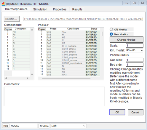
A robust thermodynamic system is the foundation for accurate rotary kiln simulations. KilnSimu uses a detailed thermodynamic system database that defines all necessary system components through a stoichiometric matrix. The database contains several phases, categorized as gaseous, mixture, and invariant phases. Each phase contains one or more constituents, with compositions expressed as amounts of system components in the stoichiometric matrix. Components are typically elements but may also include stoichiometric combinations (e.g., Ca and O versus CaO).
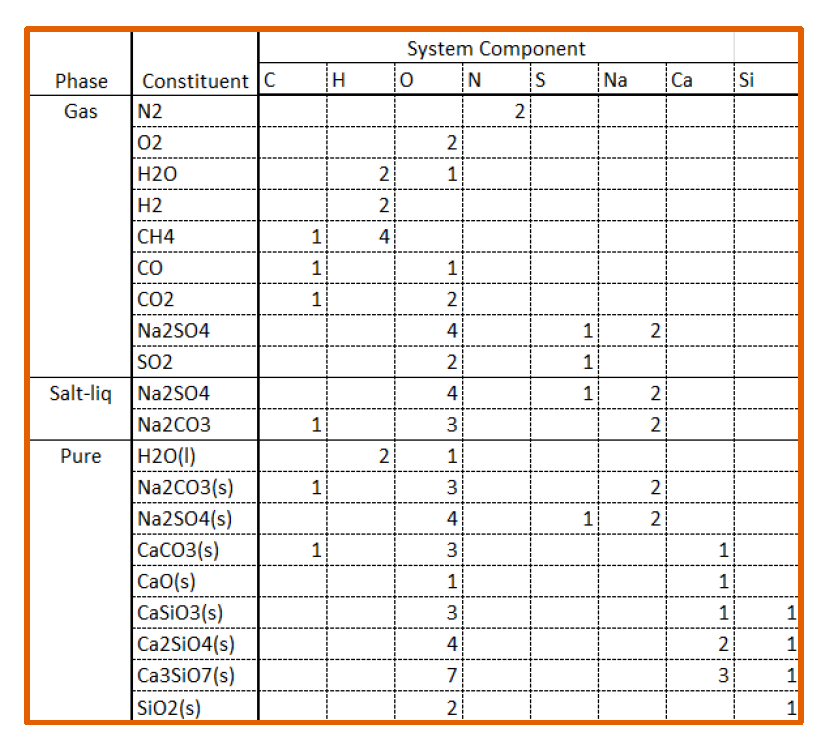
the only mixture phase is labeled “Salt-liq” with its respective constituents,
and invariant phases (solids) are listed as “Pure.”
2. FUELS
Selecting the right fuel for your kiln process
Selecting the right fuel for rotary kiln processes is crucial to achieving optimal energy efficiency and product quality. KilnSimu provides users with a variety of fuel options, each with different characteristics that affect combustion, temperature control, and emissions. By simulating different fuels or fuel blends, users can evaluate the impact of each fuel type on kiln performance. Whether using traditional fossil fuels, renewable biomass, or waste-derived fuels, KilnSimu allows users to evaluate the trade-offs between cost, efficiency, emissions, and sustainability. The software helps identify the most effective fuel strategies for any specific application, from cement production to waste-to-energy processes.
Below is a list of available fuel and waste options. These can be combined in various ratios to achieve the desired composition of sulfur (S), carbon (C), hydrogen (H), nitrogen (N), and oxygen (O), which are key components in most fuels.
- Graphite carbon (s)
- Coal char (s)
- Petroleum coke (s)
- Low-volatile bituminous coal (s)
- Medium-volatile bituminous coal (s)
- High-volatile bituminous coal (s)
- Subbituminous coal (s)
- Lignite coal (s)
- Peat (s)
- Softwood bark (s)
- Hardwood bark (s)
- Softwood (s)
- Hardwood (s)
- Wood char(s)
- Waste char (s)
- Tire waste (s)
- Refuse-derived fuel RDF (s)
- Food waste (s)
- Green waste (s)
- Paper waste (s)
3. PROCESS SYSTEM SETUP
Configuring the rotary kiln process flow
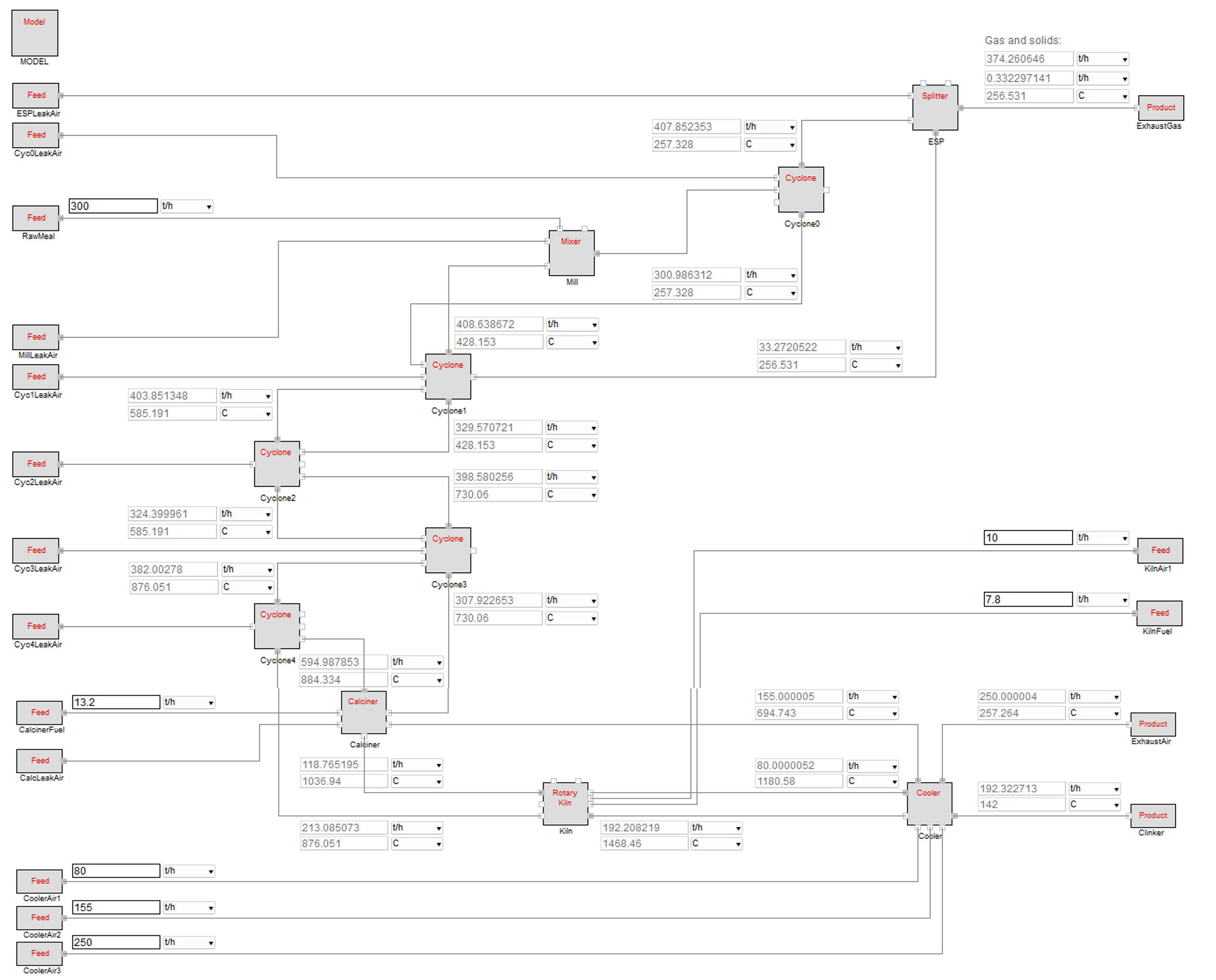
The process system setup is the basis for simulating rotary kiln processes in KilnSimu. In this step, users design the system layout by configuring various process units that will interact within the rotary kiln process. For example, in a cement production scenario, a typical system setup might include components such as a splitter, cyclones, mixers, a calciner, the rotary kiln, and a cooler, each representing key stages of the production process. These process units are represented visually in ExtendSim as large gray boxes, with lines connecting them to illustrate the flow of material between units.
Each unit can be configured with input and output flow points. Small gray boxes indicate where material exits each unit, while white boxes represent input points. Adjustable input areas, indicated by white boxes, allow the users to customize material flow rates. These adjustments are essential for simulating varying operating conditions, such as changes in feed rate or material properties. During the simulation, grayed-out boxes automatically update to reflect dynamic product flow rates, providing real-time feedback on each unit’s performance. This setup ensures that users can test different scenarios, refine process parameters, and optimize their kiln operation based on accurate, real-time simulation data.
4. MODEL BLOCK
Precise control and monitoring of every aspect of rotary kiln simulations
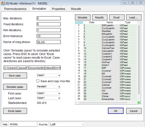
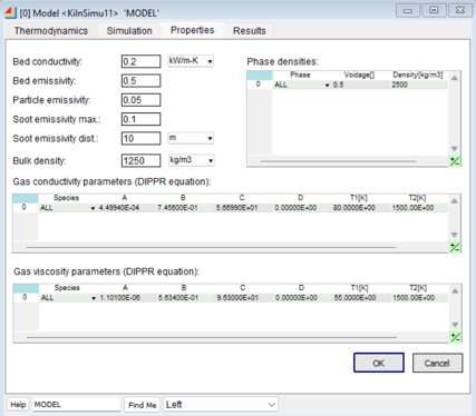
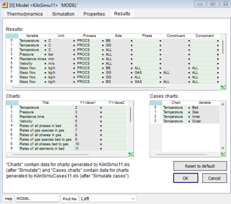
The model block is a central component of any process design in KilnSimu. It organizes the setup and execution of the simulation process and consists of four main tabs that allow the user to define key parameters and manage simulation data. Each tab serves a specific function that is essential for accurate modeling and analysis of rotary kiln operations. The tabs include:
5. PROCESS UNIT BLOCK
Fine-tuning process components for accurate and actionable simulation results
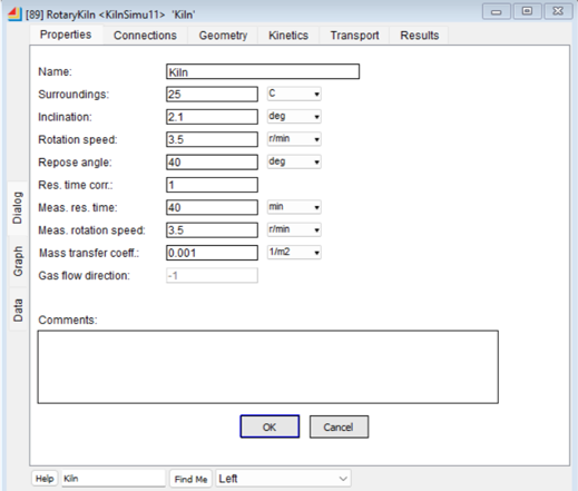
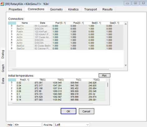
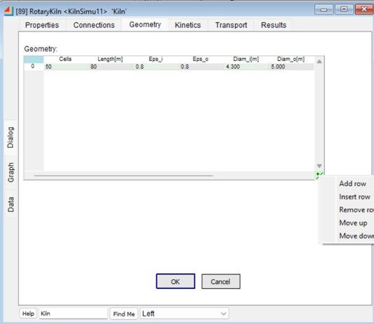
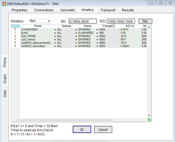
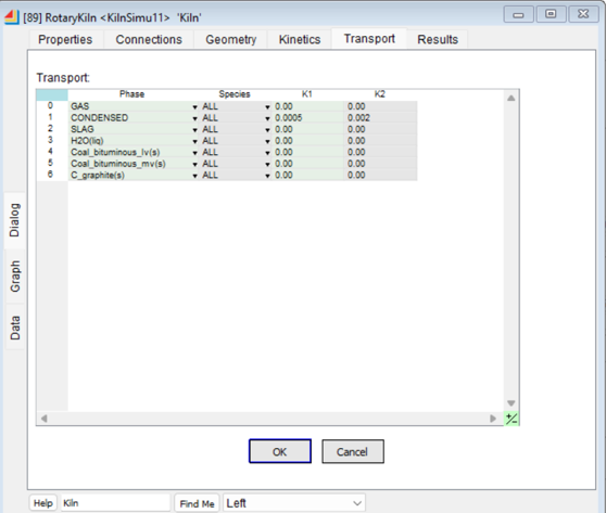
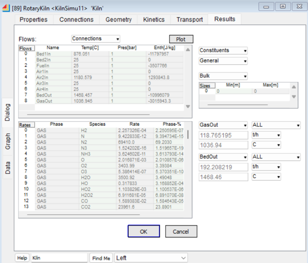
The process unit block allows users to configure and enter data for each model process unit in KilnSimu. The kiln process unit is set up through six tabs providing essential functionality to define process parameters and enable accurate modeling of rotary kiln operations. The tabs include:
6. FEED BLOCK
Controlling and adjusting the feed system for optimal rotary kiln performance
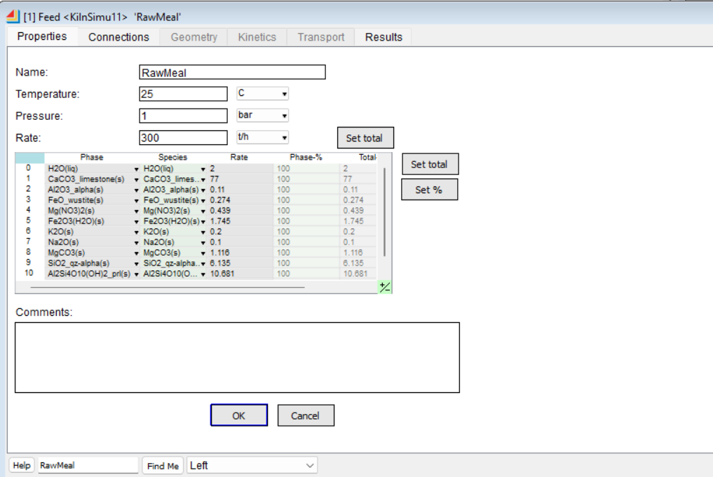
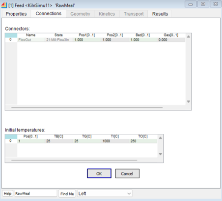
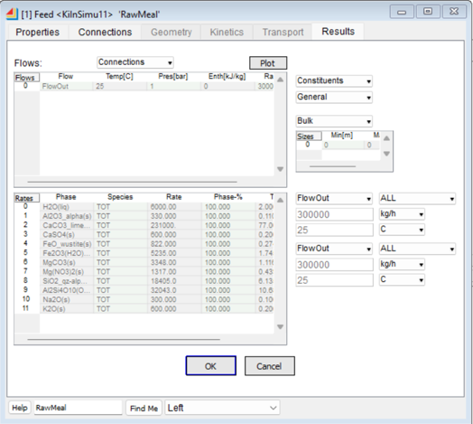
The feed block is responsible for defining the input flows to the rotary kiln in KilnSimu. It consists of three tabs that allow the user to set and manage essential parameters related to feed materials, air, and fuel. These tabs ensure accurate configuration and verification of the feed system in the simulation:
7. RESULTS
Outputs providing a comprehensive view of kiln performance to support optimization efforts
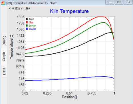
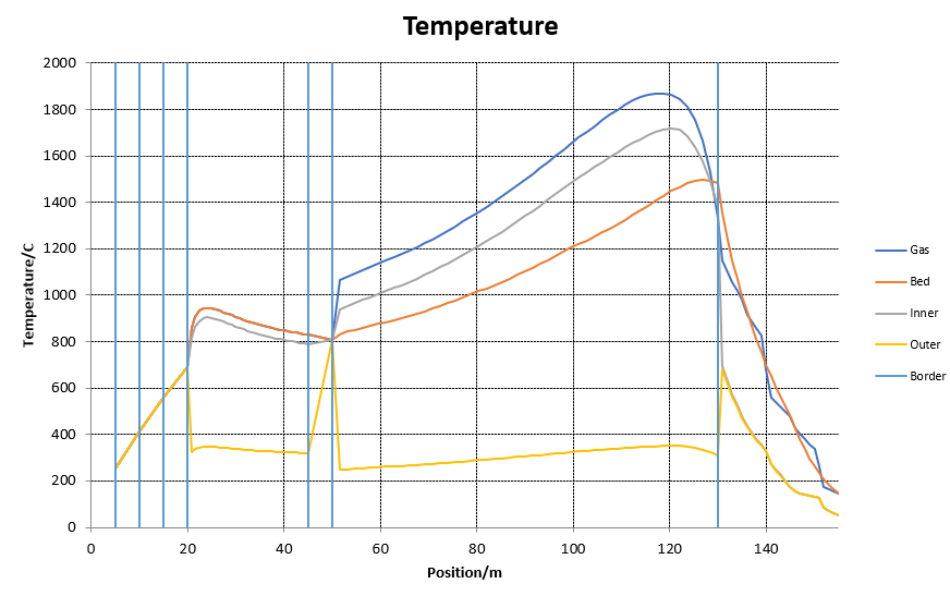
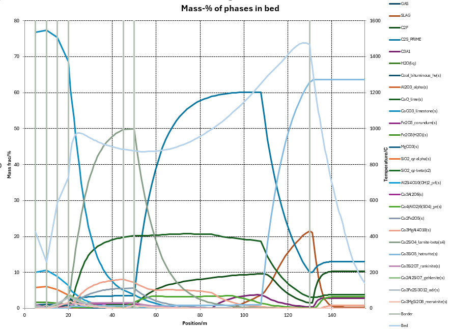
KilnSimu provides a variety of output options for analyzing and understanding kiln behavior, allowing users to gain deep insight into the process. One of the primary parameters to evaluate is temperature, with simulation results providing detailed plots of temperature variations across various kiln components such as the gas, bed, inner wall, outer wall, and kiln border. These outputs help users visualize the thermal profile of the kiln and identify potential issues.
In addition to temperature and phase distribution, users can also generate plots for the phase transformation rates, tracking the movement from bed material to gas, and the specific rates of individual phases or constituents. These outputs provide a comprehensive view of kiln performance and support optimization efforts.

